

Top Vacuum Load Break Switch Options for Reliable Electrical Distribution
2026-09-08
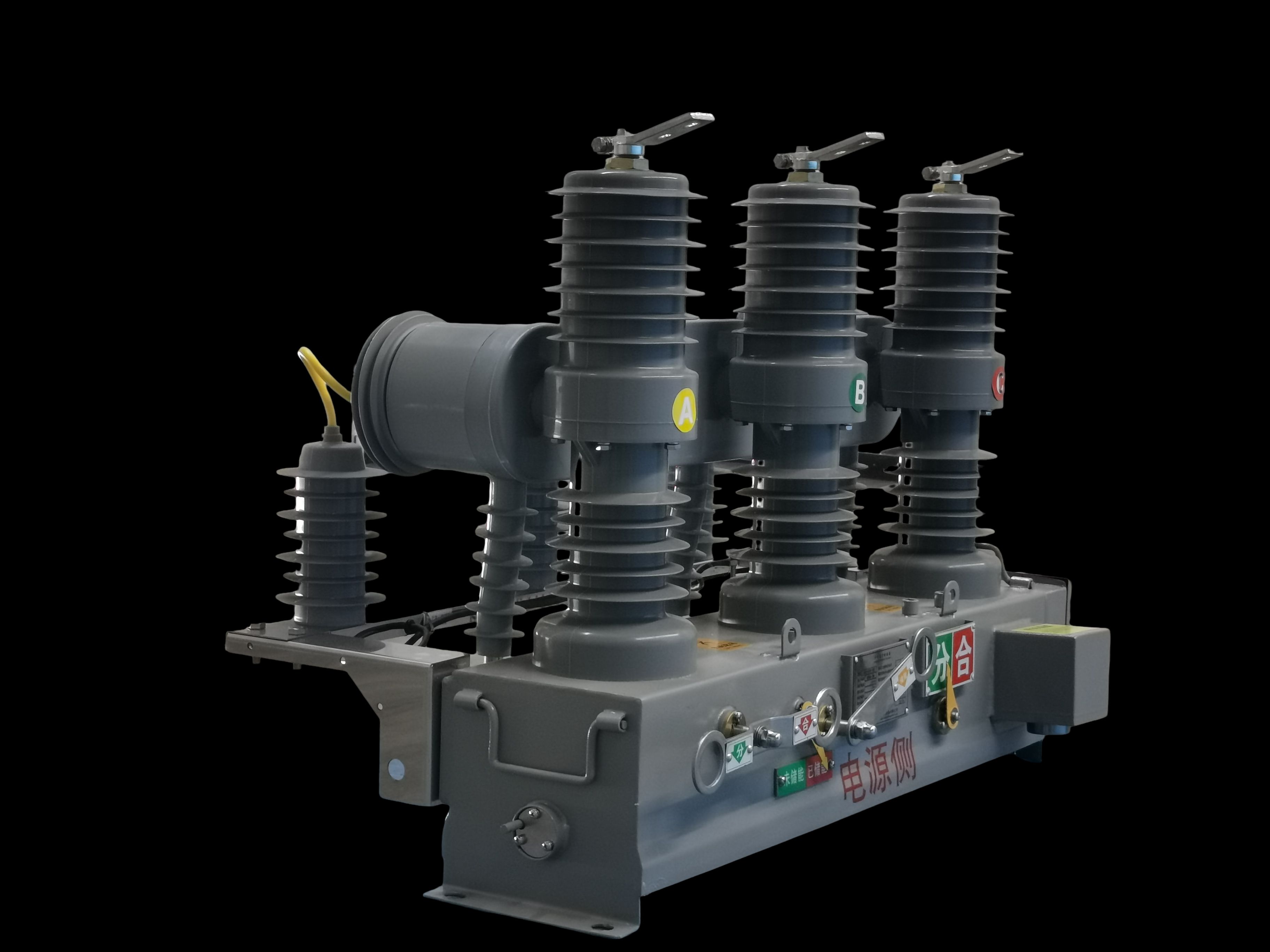
Choosing the wrong load break switch can lead to unplanned outages, equipment damage, and costly downtime. Vacuum technology offers a cleaner, safer way to interrupt load currents, but not all vacuum load break switches are built to the same standard. If you're looking for options that combine proven performance with long-term reliability, this guide is for you. We'll break down the key factors to consider and highlight top choices, including Deepwill, a brand that's gaining attention for its robust designs.
What Separates a Dependable Vacuum Load Break Switch from the Rest
Dependability in a vacuum load break switch rarely shows up as a single line on a spec sheet. It emerges from the interrupter's behavior over hundreds of operations. Contact materials that resist welding and erosion keep the arc short and contained inside the vacuum bottle, while a fast, snap-action operating mechanism stores enough energy to complete the stroke regardless of how the handle is pulled. That consistency prevents the slow, mushy switching that accelerates wear and leads to restrikes.
The rest of the picture comes down to how the switch survives its environment. A dependable unit seals the vacuum interrupter hermetically and keeps the external linkage simple enough to run for years without field adjustment. Clear mechanical position indication also removes guesswork during maintenance. When those details are handled well, the switch doesn't require constant attention and doesn't surprise operators with intermittent failure.
Field-Tested Configurations That Keep Distribution Networks Running
Every distribution network eventually hits a point where textbook designs stop matching what the field actually throws at it. That's where the battle-tested tweaks come in—things like splitting a long radial feeder into two halves with a normally open tie switch, so one fault doesn't black out every customer downstream. You learn this the hard way after three separate outages, a pile of customer complaints, and one very long night staring at a protection relay's event log. The trick isn't just having the right gear; it's knowing how to arrange it so a single failed component doesn't cascade.
Another configuration that earns its keep is the use of auto-sectionalizing reclosers on overhead lines that run through tree-heavy territory. Instead of a permanent trip on the first branch contact, the recloser cycles through a fast curve, then a slower one, giving momentary faults a chance to clear without human intervention. Pair that with a downline sectionalizer that counts fault currents while the recloser is open, and you isolate the bad span while keeping the rest of the circuit energized. It's not glamorous, but it cuts outage minutes by an order of magnitude compared to the old fuse-saving schemes everyone used to copy from aging utility standards.
For underground networks in dense urban cores, the real workhorse is the spot network with a normally closed loop and directional overcurrent relays that don't trip on reverse power flow from a fault on an adjacent transformer. Setting those relays requires field-measured impedance values, not the nameplate numbers, because cable aging and ambient soil temperature shift everything. Engineers who skip that step end up with phantom trips that vanish by the time the crew arrives—maddening for everyone involved. The tested configuration isn't a single drawing; it's a set of adjustments refined over years of comparing relay targets with what the linemen actually find when they open the vault.
Where Material Choices and Contact Design Make or Break Performance
Materials set the baseline. A copper alloy like C18070 might offer 80% IACS conductivity, but its oxide film forms within hours at elevated temperature, raising contact resistance. Adding a gold flash over a nickel barrier helps, yet if the gold is too thin or porous, corrosion creeps underneath and eats away at the underlying layer. Beryllium copper provides high yield strength for spring contacts, but its higher cost forces designers to judge whether the extra fatigue life justifies the spend. Phosphor bronze sits in between—cheaper and with decent spring properties—but its lower conductivity means more joule heating in high-current lines.
Contact design decides whether that material actually touches the mating surface. A single high-force point can punch through debris but may fret and wear quickly. Multiple dimples or a crowned blade spreads the load, yet requires tighter flatness tolerances to avoid a few contacts carrying all the current. Normal force matters less than pressure distribution: a 100-gram force on a 0.5 mm radius sphere creates a very different contact patch than the same force on a flat wedge. Practical designs often measure the real contact area through pressure-sensitive film or micro-ohmmeter mapping, because only a fraction of the apparent area conducts.
The interaction of the two is where failures hide. A hard contact with a soft plating, like gold over nickel over copper alloy, can survive thousands of mating cycles if the plating is thick enough and the underlying metal does not yield. But if the spring is too stiff, the gold wears to the nickel barrier quickly and resistance rises. Thermal cycling introduces differential expansion between brass terminals and steel screws, loosening the joint over time. Vibration can turn a static contact into a micro-fretting machine if the material pair lacks enough compliance. The most reliable designs treat material and geometry as one system, not separate choices.
Smart Ways to Match Switch Ratings to Real Load Profiles
Real loads rarely match the nameplate numbers. Instead of sizing a switch from the motor's stamped amps, grab a power logger and capture at least a week of actual current data. Look for inrush spikes, steady-state draw, and duty cycle. For example, a small conveyor motor might briefly pull six times its running current at startup, but that surge lasts only a few cycles. The switch's thermal mass can absorb short peaks without tripping or welding contacts, so you don't need to oversize just to handle startup.
Load type changes the math more than most people expect. Resistive heaters are predictable, but inductive loads like solenoids or ballasts create arcs when contacts open, and capacitive loads such as LED drivers cause high inrush. Check the switch's AC rating against the actual power factor and, if you're working with DC, verify the DC breaking capacity—AC ratings often look huge but become useless at 48 VDC. Also account for ambient temperature: a switch rated 10 A at 25°C inside a sealed enclosure that runs at 60°C may only handle 7 A. Use the manufacturer's derating curve instead of guessing.
Harmonics from VFDs and switching power supplies can push real heating above what a basic clamp meter shows. Measure with a true-RMS instrument, not an average-responding one, because distorted current waveforms make thermal elements run hotter than the fundamental current suggests. After installation, do a quick spot check under worst-case load after an hour of operation—if the switch body feels more than warm or you smell hot plastic, the match is off. Revisit the profile every couple of years because loads drift, and a switch that worked fine at commissioning can become the weak point later.
Avoiding the Hidden Failure Points in Vacuum Interrupters
Vacuum interrupters often fail long before any visible sign appears on the breaker housing. The usual suspects are not the main contacts but the stainless steel bellows that allow movement while sealing the vacuum. Over thousands of operations, micro-cracks develop at the weld seams where the bellows meet the end plate. These cracks rarely cause immediate leakage; instead, they admit trace amounts of gas over months, slowly degrading the vacuum level until the interrupter can no longer clear a fault. Spotting this early requires periodic vacuum integrity tests, not just a visual check during routine maintenance.
Another failure point hides in the arc control structure, particularly the slotted copper-chromium contacts. During high-current interruptions, localized melting and splashing can deposit a thin metal film on the ceramic insulators. That film eventually forms a conductive path from the live contact to the grounded flange, leading to a flashover that trips the breaker at the worst possible moment. A careful inspection with a borescope or a very low-voltage insulation resistance test can reveal the early stages of this contamination before it becomes a hard fault.
Field experience also points to misalignment between the movable stem and the fixed contact after years of mechanical wear in the operating mechanism. Even a fraction of a millimeter of lateral shift changes the contact wipe and compression, which produces uneven heating and accelerates erosion. Technicians often assume the vacuum interrupter itself is faulty and replace it, only to have the new unit show the same symptom later. Checking the mechanism's alignment and the interrupter's mounting tolerances together prevents this cycle of repeated replacements.
Installation Practices That Extend Service Life Without Extra Cost
Many installation failures trace back to simple alignment and support mistakes, not material defects. Taking the time to align mating surfaces before tightening, spacing supports according to the manufacturer's chart, and using a calibrated torque wrench costs nothing extra but prevents stress cracks, leaks, and premature wear. On piping systems, even a 2-degree misalignment at a flange can create a constant bending load that shortens seal life dramatically.
Cleanliness at the joint is another zero-cost practice that often gets skipped. Burrs, metal shavings, or old gasket residue left from disassembly will compromise the new seal or bearing surface. A quick pass with a deburring tool, wiping down threads with a lint-free cloth, and applying only the compatible lubricant recommended by the manufacturer removes contamination risks without any added budget line.
Finally, look for built-in features that are already there to handle movement and expansion. Flexible connectors, slotted mounting holes, and breather vents are often ignored or improperly locked down during installation. Leaving those features free to function as designed—rather than rigidly fixing every point—allows the component to handle thermal cycling and vibration. That one adjustment in mindset extends service life without buying a single extra part.
FAQ
Vacuum interrupters eliminate the need for arc-quenching media like oil or SF6, so there's no risk of leakage or contamination over time. The sealed contacts operate in a near-perfect vacuum, which keeps erosion minimal and lets the switch handle thousands of operations without a drop in interrupting capability. That's why utilities often favor them for feeders where space is tight and environmental rules are strict.
The arc is drawn and extinguished inside a sealed vacuum bottle, so the contact surfaces stay clean and don't oxidize. Air-break switches suffer from moisture ingress and dust accumulation, while oil switches can develop sludge and require periodic filtration. Vacuum bottles, by contrast, are sealed for life and typically need no internal inspection for decades. That translates directly into fewer unplanned outages on a distribution loop.
Look closely at the rated voltage, continuous current, and short-circuit making capacity. The making capacity often gets overlooked, but it's what protects the switch if it closes onto a fault. Also check the mechanical endurance class (M2 or M1) and the electrical endurance class (E2 or E1) because those tell you how the switch will behave after years of repetitive duty. For overhead line feeders, a higher creepage distance may be necessary in polluted or coastal areas.
Yes, and that's one of their strongest selling points. The contact erosion in a vacuum interrupter is extremely low because the arc is diffuse rather than concentrated at a single point. Field records from distribution automation projects show some vacuum switches exceeding 10,000 load-breaking operations without contact replacement. The limiting factor is usually the mechanical mechanism, not the vacuum bottle itself.
Underground vaults, pad-mounted enclosures, and indoor metal-clad switchgear are all good fits. Vacuum load break switches don't vent hot gases or produce arc byproducts, so they're safer in confined spaces. They also handle high humidity and salt-laden air better than air-insulated designs because the interrupting contacts are sealed away from the ambient environment.
The mechanism is where most failures actually occur, not the vacuum interrupter. Look for a design with a stored-energy spring mechanism rather than a simple manual toggle, because the spring guarantees consistent contact opening and closing speed regardless of how fast the operator moves the handle. A motorized option with remote control and position feedback also reduces the need for crews to physically visit the switch, which is a real advantage during storm restoration.
Several established names come up regularly in utility specifications: Eaton's VCP-W, ABB's NAL/NALF, Siemens' 3AH, and Schneider Electric's LF series. These product lines have been on the market long enough to accumulate a solid track record of type-test certifications and field performance data. However, many regional manufacturers like Tavrida Electric and Lucy Electric also offer reliable alternatives with simpler, more maintainable mechanisms.
Since the vacuum bottle is sealed, maintenance focuses on the external mechanism and insulation. A simple visual check for moisture, dust, or cracked bushings every couple of years is usually sufficient. Lubricate the operating linkages according to the manufacturer's schedule, and periodically verify the contact wear indicator if one is fitted. No internal contact cleaning or oil changes are ever required, which keeps lifecycle costs low.
Conclusion
A dependable vacuum load break switch rarely stands out on a spec sheet alone; it earns that status through details that are easy to overlook during procurement. The first thing to scrutinise is the interrupter's contact geometry and material pairing. Copper-chromium contacts with a carefully machined spiral or axial magnetic field profile reduce localised heating and arc erosion far better than generic designs, and that directly shapes how long the switch survives repeated interruptions. Field-tested configurations matter just as much: enclosures that keep moisture and dust away from the vacuum bottle, plus simple mechanical linkages that do not rely on constant adjustment, tend to be the ones utilities leave in service for decades. Hidden failure points often creep in through poor bellows sealing, substandard getter material, or inadequate vacuum monitoring, so asking how a manufacturer verifies vacuum integrity over time is not a minor detail. Smart installation practices, such as torque-controlled bus connections and avoiding cable strain on bushings, extend service life without adding cost, because they prevent the slow mechanical loosening that eventually causes hot spots and false trips.
Matching switch ratings to actual load profiles is another area where many distribution networks overspend or undersize. Rather than defaulting to the highest interrupting rating, a closer look at fault current availability, switching frequency, and inrush characteristics of downstream transformers often reveals that a mid-range vacuum load break switch will operate more comfortably and with less maintenance than an oversized unit that rarely sees its rated stress. In practice, reliable distribution depends on choosing options that balance short-circuit performance with daily switching duty. Switches built for frequent capacitor bank or loop switching, for instance, benefit from reinforced arc control and faster operating mechanisms, while a feeder tie switch may prioritise a compact footprint and simple manual operation. The best options pair honest ratings with real-world endurance test data, not just catalogue numbers. When material choices, contact design, installation habits, and load-profile matching come together, the result is a switch that keeps distribution networks running without surprises, and that is the practical definition of reliability.
Contact Us
Contact Person: Julion
Email: [email protected]
Tel/WhatsApp: 8617351370631
Website: https://www.deyunelectric.com