
Top Plate Heat Exchanger Designs for Reliable Thermal Performance
2026-11-21
Not every plate heat exchanger is built to keep its cool when thermal loads shift. The right design choices—plate pattern, gasket placement, and flow arrangement—separate dependable performance from costly downtime. Here, we explore the top configurations that earn their place in demanding systems, with insights from ROTER on what really drives long-term reliability.
What Changes When Plate Packs Run at Full Thermal Load
Running a plate pack at full thermal load changes more than just the outlet temperature. The approach temperature shrinks, the log mean temperature difference gets tighter, and the heat flux across each plate climbs. This pushes the unit closer to its hydraulic and thermal limits, where small shifts in flow or fouling become far more noticeable. Plates that once had comfortable margins now operate with less tolerance for uneven distribution, and the risk of local hot spots or channel maldistribution starts to climb.
Pressure drop also behaves differently near full load. As flow rates rise to meet the demand, velocities through the narrow gaps increase, and the resulting turbulence helps heat transfer but adds strain on the gaskets and plate alignment. You may see a sharper rise in differential pressure than predicted by simple linear scaling, especially if the original sizing assumed a lower operating point. This means the pump curve, bypass valve, and control logic all need to be rechecked rather than just tweaked.
Another shift happens on the maintenance side. Full thermal load accelerates the buildup rate of scale or biofilm because higher wall temperatures and faster evaporation at the surface concentrate dissolved solids more aggressively. What was a six-month cleaning interval might shrink to four months or less. Operators who track actual duty against design duty often notice that the safety factor quietly disappears, leaving the plate pack with almost no reserve for a sudden increase in demand or a drop in cooling water temperature.
Corrugation Profiles That Balance Heat Transfer and Pressure Loss
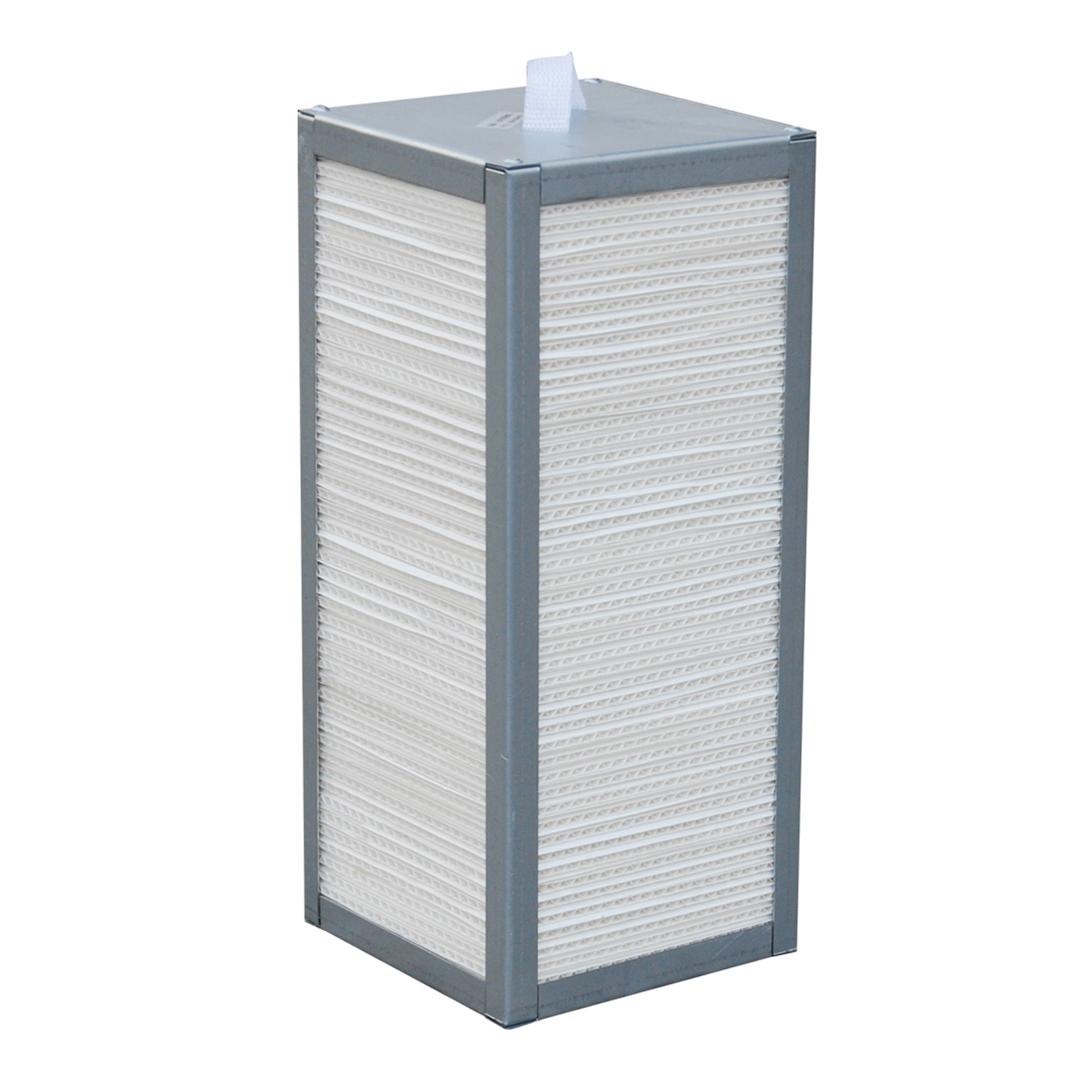
Corrugation depth and pitch move heat transfer and pressure loss in opposite directions. Increasing the amplitude tends to stretch the boundary layer and create stronger recirculation zones behind each crest, which raises the Nusselt number. The same geometry, however, narrows the effective flow cross-section and forces the fluid through sharper directional changes, so the friction factor climbs far more steeply once the corrugation angle exceeds a certain range. Profiles that perform well usually keep the crest radius generous and avoid steep ridge flanks, allowing secondary vortices to do the mixing without turning the whole channel into a series of abrupt expansions and contractions.
The asymmetry of the profile matters just as much as its height. A skewed wave with a longer upstream face and a shorter downstream face can shift where separation begins, reducing the low-velocity pocket behind the peak while still disturbing the thermal boundary layer. This kind of tailored geometry produces a more even wall temperature distribution because the fluid is not allowed to linger in dead zones that would otherwise insulate the surface. In practice, a moderately rounded trapezoidal or sinusoidal profile with a mid-range pitch-to-amplitude ratio often provides a better compromise than aggressive herringbone patterns, especially when pumping power is limited.
The right balance also depends on the operating point. At lower Reynolds numbers, the pressure penalty from a pronounced corrugation is small relative to the gain in heat transfer, whereas at higher Reynolds numbers the same profile may waste energy through vortex shedding and form drag. For that reason, balanced profiles are rarely universal. They are selected by matching the corrugation geometry to the expected flow regime and by checking that an increase in heat transfer still outweighs the added hydraulic resistance at the design flow rate.
Material Pairs Built for Thermal Cycling and Aggressive Fluids
A material that survives a steady chemical bath can fail quickly once temperature swings enter the picture. With thermal cycling, two adjacent components expand and contract at different rates, so the real weak point is often the interface rather than the base material itself. Pairing a high-strength alloy with a properly chosen polymer or ceramic insert gives the joint enough compliance to absorb that differential movement while still keeping the fluid at the seal face. In aggressive-fluid service, that combination matters more than upgrading a single component.
For chlorine-rich process water and hot acids, carbon-filled PTFE against super duplex stainless steel remains one of the more reliable pairings. The filled PTFE resists extrusion and keeps its creep low as temperatures swing, while the duplex alloy brings strong resistance to pitting where chlorides concentrate. In pumping and valve trim, this pairing handles repeated start-stop cycles without the polymer hardening or the metal losing passivation. Another effective match is PEEK with titanium for sulfuric and nitric streams, provided fluoride contamination is absent.
The selection has to look beyond chemical compatibility. Galvanic potential, surface finish at the sealing land, and thermal conductivity all affect whether a pair lasts. A rough metal face can shred a softer polymer during expansion; a conductive ceramic coating can pull heat away from an elastomer that would otherwise age too fast. That is why well-designed assemblies often pair a corrosion-resistant metal with a softer, creep-controlled polymer or a ceramic, then specify the mating finish and preload together. Without that system-level fit, even chemically compatible materials can open a leak path after a few hundred cycles.
How Uneven Flow Distribution Quietly Cuts Thermal Duty
Flow distribution problems rarely announce themselves through alarms. A heat exchanger can leave the factory with a carefully calculated duty based on uniform velocity and temperature profiles, yet in service the actual flow splits unevenly across passes, channels, or tube rows. Small differences in header geometry, inlet nozzle placement, bundle tolerances, and even fouling patterns are enough to starve part of the surface while pushing excess flow elsewhere. Because the mixed outlet temperature may still look reasonable, the shortfall in thermal duty often goes unrecognized until downstream conditions begin to drift.
The loss mechanism is not simply a matter of less liquid touching the surface. In the low-flow zones, the local heat transfer coefficient drops and the fluid reaches the outlet temperature earlier, so those regions contribute very little additional heat pickup. Meanwhile, the high-flow zones operate at a reduced temperature change per unit volume and may not compensate for the starved areas. Over time, this imbalance accelerates fouling in the slow regions because deposits accumulate more easily where shear is lower, which further redistributes flow and quietly erodes capacity. The exchanger may still hold full pressure drop or pass a routine check even as several percent of its thermal duty disappears.
A more revealing test is to compare actual duty against the design curve under stable operating conditions, or to look for a narrowing of the hot-side and cold-side temperature approaches that cannot be explained by simple load changes. When those indicators appear, the usual first step is to inspect the inlet distributor, pass partitions, baffle arrangement, or any modification that changed the hydraulic path. In many cases, correcting the distribution restores more duty than cleaning the entire bundle because it returns the full surface to active, balanced service.
Gasket Grooves and Plate Alignment as Overlooked Leak Paths
Most leak investigations start with the gasket itself, yet the groove it sits in rarely gets the same attention. A slightly deformed or corroded groove floor can hold the gasket unevenly, creating localised compression loss that no amount of retorquing will fix. Once the plate pack is under pressure, fluid finds those low spots and works outward along the groove wall, often leaving a stain pattern that points away from the gasket as the root cause.
Plate alignment adds another layer. Even small offset between adjacent plates can shift how the gasket contacts the sealing surface, particularly near the portholes and the bottom edge where drainage collects. Over repeated thermal cycles, that offset becomes a worn track rather than a single failure event. Checking diagonal measurements and hanger alignment before tightening is more reliable than chasing seepage after the fact.
What makes these two paths easy to miss is that they rarely show up on a hydrostatic test with cold water. The leak appears later at operating temperature, when thermal expansion changes the groove width and plate position. Marking suspected areas before disassembly, then comparing groove depth and plate-to-plate offset with a straightedge, usually reveals a pattern that a visual check alone will not.
Frame Geometry That Keeps Service Work From Eating Into Uptime
The geometry doesn't just create open space; it positions that space where a technician will actually stand or kneel. Wear items like filters, sight gauges, and drain valves sit proud of the main frame rails instead of being tucked behind crossmembers. That means a quick daily check involves loosening one cover and reaching straight in, not removing three unrelated panels to get a line of sight.
High-touch service points are grouped into shallow, outward-facing bays rather than scattered across the machine. The lower rail drops away just enough to let a battery or hydraulic pump slide out on its own mount, so there's no need to lift the cab or disconnect a bundle of hoses first. Hose and harness paths follow the frame's straight runs, with gentle bends and clamped standoffs that keep rub points visible before they become failures.
Panel fit matters as much as bolt access. The frame is jigged so that guards and belly plates return to the same position without prying, even after repeated removal. Weld seams are kept away from high-stress joints where flex can start hairline cracks, and the few brackets that do carry load have slotted holes to absorb misalignment during reassembly. The result is less time fighting the structure and more time keeping it working.
FAQ
Corrugations create constantly shifting flow paths that break up the boundary layer. Even at lower velocities you get turbulent mixing, which drives up the heat transfer coefficient without needing a larger footprint.
Many designs use variable chevron angles or mixed high and low theta plate packs. This lets the same unit handle high pressure drop and high recovery conditions as well as low flow turndown without losing too much effectiveness.
Thermal conductivity, fouling tendency, and mechanical fatigue all interact. A thinner highly conductive plate may transfer heat well, but if it fouls faster or fails under pressure cycling, the real-world performance suffers.
The inlet area has to spread fluid evenly across the full plate width before it reaches the main corrugated field. Poor distribution creates dead zones and uneven temperatures, so some designs add slotted or diagonal feed sections to correct this.
It depends on the duty. Brazed units eliminate gasket degradation and handle higher pressures, but they are less forgiving when opened for cleaning. Gasketed units are easier to inspect and resize, so they are often preferred where fouling or changing process conditions matter more.
High local shear from corrugations keeps particles suspended, and a lower residence time in narrow channels reduces deposition. Some plates also use mirror-finish surfaces or wider gaps on the fouling-prone side to slow the buildup.
With a frame-and-plate design you can add or remove plates to adjust capacity rather than replacing the whole unit. The ability to rearrange the plate pattern or change the pass arrangement makes the exchanger adaptable without a full redesign.
Steeper chevron angles increase turbulence and heat transfer but also raise pumping cost. The reliable approach is to match the plate geometry to the allowable pressure drop for each stream rather than chasing the highest possible U-value.
Conclusion
Plate pack performance at full thermal load rarely degrades in a straight line. Once a unit pushes toward its rated duty, small inconsistencies in corrugation depth, pressing tolerance, or port alignment become magnified. The best designs pair heat transfer with pressure loss by using variable-angle chevron patterns or mixed high/low chevron-angle plates, so a given channel no longer forces the same compromise between turbulent film and pumping cost. Material selection follows the same logic. Rather than defaulting to 316 stainless, reliable units match plate alloy, gasket compound, and frame coating to the actual thermal cycling range and the aggressive species in the process stream. This keeps stress corrosion, chloride pitting, and fatigue cracking from showing up after only a few hundred cycles.
Uneven flow distribution is a quieter failure mode. Maldistribution often starts at the inlet manifold or with oversized port nozzles, and it shaves thermal duty even when overall pressure drop looks normal. Quality designs use wider distribution zones, angled port entries, or baffled inlet paths to force fluid through the full plate width. Gasket grooves and plate alignment deserve the same attention. A gasket that sits too deep or a plate that hangs slightly off the carrying bar may pass a cold hydro test and still weep under thermal movement. Finally, frame geometry matters for uptime. Tensioned tie rods, properly set carrying bars, and enough pull-out clearance turn routine opening, cleaning, and re-torquing from a half-day job into something a crew can finish without disturbing adjacent plates.
Contact Us
Contact Person: Rhea
Email: [email protected]
Tel/WhatsApp: +8618800560886
Website: https://www.rotorairtech.com